1958 Douglas 92L2 update 3
The original 8″ wheels on this have now been upgraded to 10″ with the standard PX wheel on the back and a ScootRS, atomic branded, GS150 replica conversion rim on the front. The front wheel has plenty of clearance from the guard and with the new Gabriel spring and shock absorber kit, it is miles better than the original. This is the first time I have used the Gabriel shocks and they were well priced so I’m not expecting Bitubo performance but they have to be better than the originals on the road and under braking. I will have to wait and see how they go.
The speedo is the original Veglia unit in MPH and if you are going to replace the cable make sure the hole in the fork is big enough for the outer as some newer cables are a lot thicker than others. It’s the same with the front brake cable, check the outer will go down the fork and out through the bottom as there isn’t much room in there and the only place to make it wider would be by drilling into the axle, probably something you don’t want to do.
Cabling
The control cabling on these old handlebar scooters is a little different to an enclosed headset type like the sportiques and supers and before you decide to change the cables for new ones, make sure you can buy ones for wideframes. SIP sell them and you can get them off EBay but the PX/VBB/etc ones are too large in diameter for the holes in the handlebar. I couldn’t get the handlebar out of the headlight casting so drilling holes in the handlebar wasn’t an option for all of the cabling. If you can get the handlebar off, then this isn’t too bad of a job.
Its quite a fiddly job getting the throttle and brake cable along the inside of the handlebar to the right position while it is in place. The factory throttle assembly on these has the cable connected to a shaped, flat piece of steel and the original cable had a ferrule on the end of it for this purpose. You could crimp a ferrule onto the cable or what I did was to just use a screw connector similar to the gear cable screw connectors. As the throttle tube is rotated, the flat piece of steel is drawn along grooves in the tube, pulling the cable.
The clutch cable wasn’t too bad and the gear cables are routed externally anyway. You will need reasonably long gear and throttle cables depending on how you have to route them and if you are lucky the internal tubes, that the cables are run through in the floor of the frame, are clear. My gear cable tube had 2 ends off the old cable outer stuck in there and that made it very frustrating to pull 2 new cables through however once you get all the control cables done then you can concentrate on the electrical system.
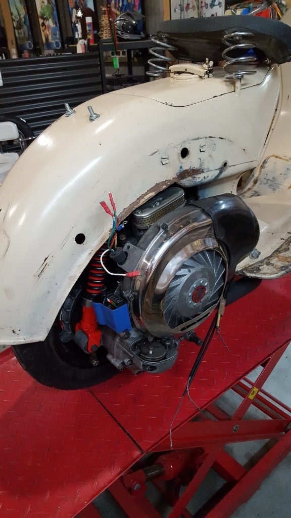
On my scooter the throttle cable came out in the old carburettor compartment and the wiring for the front of the scooter came out on the opposite side. I tend to use my own cable loom, made with wiring from a local electrical wholesaler and following standard colours where possible instead of buying one. Its basically the same wiring on all of my non battery scooters, except with some minor differences around the brake switch or horn and I just keep a copy of the diagram on the wall. All of my non battery scooters are 12v electronic ignition with 3 pole regulator (4 pole for battery scooters) and I have found this to be very reliable.
Lighting 1958 Douglas 92L2 update 3
This scooter had a GS/Sportique acorn type tail light on it when I got it so I will just re-use it with 12v bulbs. I dont think any of the original wideframes actually had a brake light however by using a PX inline front brake switch on the new rear brake cable, I should be able to get this working OK. The handlebar light switch is a thing of beauty and attaches to the throttle assembly via a screw in the switch however terminating the wires in the small space available can be a challenge.
Basically each switch position covers or uncovers terminals as the switch mechanism slides over them. The first position on the switch is to the left and this is just a push on, for the kill switch. then you have the headlight low/high and pilot light positions. The horn is just a plastic push tab that earths a copper connector directly onto the handlebar. The switch itself has rather small copper terminals that you can slide your cabling under however you may want to tin these first and then try to solder the wires on with out making one big mess. Good luck with that.
Once your cabling is run you can then cut the cable covers to length for the gear cables and the switch wiring cable. Make sure you put the triangular gear change rubber cover on before terminating the gear cables on the handlebar.
Hopefully we aren’t too far away from starting it up although the weather here is crap for riding it at the moment.
Looking for parts or need help with your Douglas – Contact us
1958 Douglas 92L2 update 3
